BusbarSection
| description |
This document describes the BusbarSection as part of the modelling-guidelines for the NBNL Profile Group. |
| version |
current |
| author |
Arend Hagreis, ahagreis@netbeheernederland.nl |
| feedback |
Introduction
This document is part of the grid modelling approach and details the grid model data requirements for data supplied by Dutch transmission and distribution system operators and describes in detail the Busbar Section.
Most of the terms in this document are used within the energy industry, particularly in standards like the IEC Common Information Model (CIM).
Dutch translation of Busbar Section is Rail
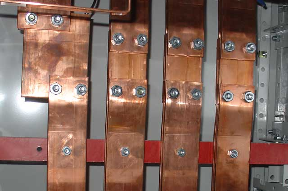
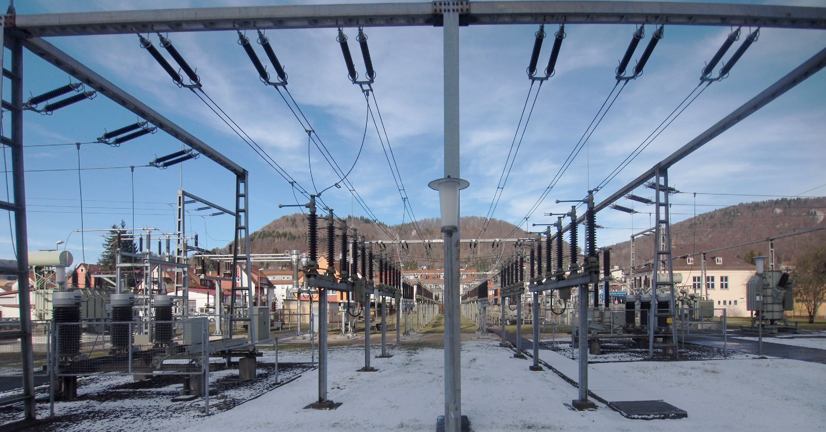
A busbar section is in most cases a metallic strip or bar, typically housed in and part of enclosures (in substations) for the distribution of high current power. However, they can also be used based on flexible or rigid busbars to connect high-voltage equipment in electrical switchyards.
Definition
The busbar section is a conductor, or group of conductors, with negligible impedance, that serve to connect other conducting equipment within a single substation. The busbar section may have many physical terminals but in CIM the busbar section is modelled with exactly one logical terminal.
Core entities
In CIM, a busbar section is modelled with a cim:BusbarSection object associated via its cim:Terminal to a cim:ConnectivityNode object.

Modelling choices
In cim the ConnectivityNode objects are the means by which connectivity (see Connectivity) is described and a typical grid model has many ConnectivityNode objects that do not represent busbars. Only Connectivity Nodes that have the Terminal of a BusbarSection associated with them are representing a cim:BusbarSection.
A busbar can have different layouts based for the usage in a cim:VoltageLevel, see BusbarConfiguration.
For the containment of the BusbarSection the association Equipment.EquipmentContainer is required and shall point to EquipmentContainer of type VoltageLevel or Bay (when a disconnector is splitting a busbar section in two).
Voltage measurements are typically obtained from Potential Transformers (PT) that are connected to busbar sections, see also Measurements and Power Transformer.