Low-Voltage Distribution Cabinet
| description |
This document describes the Low-Voltage Distribution Cabinet as part of the modelling-guidelines for the NBNL Profile Group. |
| version |
dataset-metadata (draft) |
| author |
Arend Hagreis, ahagreis@netbeheernederland.nl |
| feedback |
Introduction
In the Common Information Model (CIM) (IEC 61970/61968), a low-voltage street distribution cabinet (also known as a feeder pillar, distribution board, or wijkkast in Dutch) is not modelled as a single object. Instead, it is modelled as a combination of logical and physical components within the Equipment and Topology profiles.
The exact modelling approach depends on the required level of abstraction (e.g., for power flow analysis or asset management). Below is the standard method for structuring a distribution cabinet functionally and topologically.
The Base Structure of the Cabinet
-
cim:Substation or cim:Bay (Container): Although a street cabinet is physically not a large high-voltage substation, CIM uses the Substation class and the specific distribution containers like Bay as the organisational container. This ensures all internal components are logically grouped together.
-
cim:EquipmentContainer: This is the abstract class from which Substation and Bay inherits. The container is used to specify that the busbars and fuses are physically located inside the cabinet.
Modelling Internal Components
Inside the container, you model the physical electrical components that transport and protect the power:
-
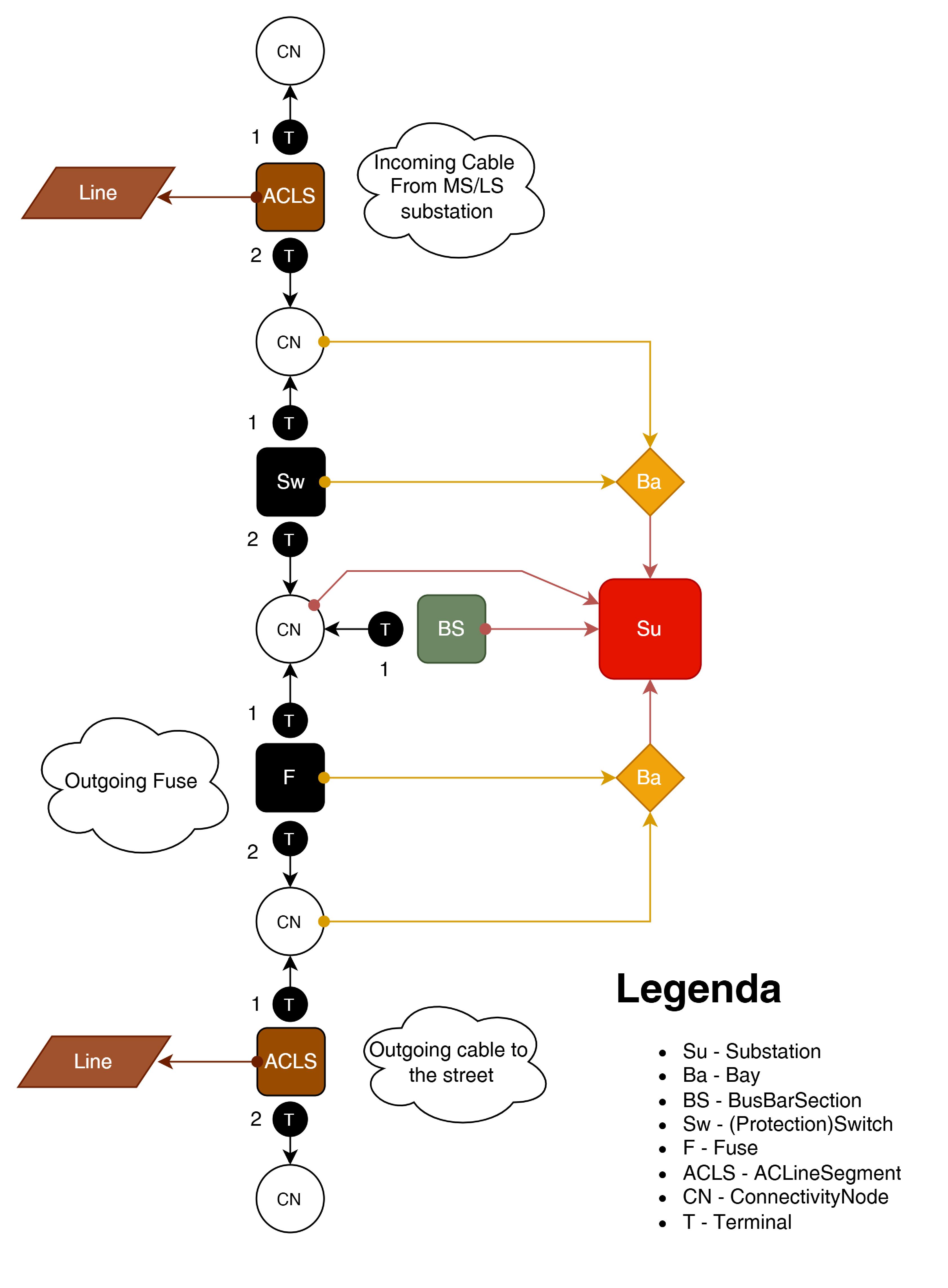
cim:BusbarSection (The Busbar): The internal copper bars (usually a 3-phase busbar system) where the incoming feeder cable enters and the outgoing lines to the consumers connect.
-
cim:Fuse or cim:Switch (Protection/Switching): Every outgoing cable (and often the incoming supply) is protected by fuses. In CIM, you model this using the cim:Fuse class. If a main switch is present, you use cim:Disconnector or cim:LoadBreakSwitch.
-
cim:ACLineSegment (Cables): The incoming underground cable from the transformer station (MV/LV) and the outgoing low-voltage cables to the end-users (cim:EnergyConsumer) connect directly to the cabinet’s components.
(Topological) Connectivity
To enable network calculation software (such as for load flow analysis) to understand the power flow, you connect the components using the CIM node-breaker or bus-branch model:
-
cim:ConnectivityNode: These are the logical nodes. You need at least one ConnectivityNode for the BusbarSection itself, and separate nodes before and after each Fuse.
-
cim:Terminal: Every physical device (cim:BusbarSection, cim:Fuse, cim:ACLineSegment) has one or more Terminal objects. You link these terminals to the correct ConnectivityNode.
Logical Power Flow Structure
In most cases a cabinet has a single incoming feeder cable (from the transformer station) and multiple Bays and outgoing cables to the end-users. The diagram above shows the logical connectivity of the components inside the cabinet.
Asset Data & Location
If your model is also used for asset management (GIS / ERP systems), you can add the following classes:
-
cim:Asset: Links physical attributes (brand, type, manufacturing year, maintenance status) to the logical CIM electrical components.
-
cim:Location and cim:PositionPoint: Used to store the exact geographical GPS coordinates of the street cabinet.
Background
For more information see:
-
Containment for a detailed description of the containment of equipment in a cim:Substation class.