Operational Limit
| description |
This document describes the Operational Limit as part of the modelling-guidelines for the NBNL Profile Group. |
| version |
current |
| author |
Arend Hagreis, ahagreis@netbeheernederland.nl |
| feedback |
Introduction
This document is part of the grid modelling approach and details the grid model data requirements for data supplied by Dutch transmission and distribution system operators and describes in detail the Operational Limit .
Most of the terms in this document are used within the energy industry, particularly in standards like the IEC Common Information Model (CIM).
The Operational Limits are used to define the voltage, current and power limits (maximum or minimum) that can flow through a piece of equipment. For example, the active power limit is used to define the maximum active power of an equipment.
The total allowable power (the technical limit) of a device is based on the voltage, current, and permissible temperature development. Normally, the direction of current is irrelevant to the power limit; the limit is the same in both directions (PATL - Permanent Admissible Transmission Loading).
However, due to guidelines, policy frameworks, contractual agreements, etc., the permitted capacity for, for example, feed-in may be higher than the consumption by the device. In these cases, as a result of policy measures, the device has more than one limit (PATLT - Permanent Admissible Transmission Loading Threshold). This requires a clear method for defining a direction.
Often, the limits are determined based on the normal state (the situation in which the grid is calculated), but in situations (usage scenarios) where the direction of the current is relevant, the direction of the current through a device can change as a result of, for example, a switching action. And with that, the direction/potential of the limit also changes.
*) note: The OperationalLimitType.kind (PATL,PATLT, etc) are not part of the NBNL EQ profile, the assumption for now is that the PATLT the default is.
One of the use cases for the cim:OperationalLimit is in the capaciteitskaart where it is used to define the Aanwezige TransportCapaciteit (ATC).
Core entities
Types of Operational Limits
Basically there are four types of operational limits defined and depending on the requirements of the specific application can be defined in terms of:
The Limit is associated with an OperationalLimitSet and has a flow direction defined by the attribute PositiveFlowIn.
Operational Limit structures
There are two structures for operational limits: the OperationalLimitSet and the OperationalLimitType (*). The cim:OperationalLimitSet is used to group together different types of operational limits that apply to a specific piece of equipment, while the cim:OperationalLimitType is used to define the specific properties of a limittype (e.g., duration, kind (patl, patlt) and directionkind (abs, low, high)) that applies to the equipment.
*) note: OperationalLimitType is not (yet) part of the NBNL EQ profile.
OperationalLimitSet
The OperationalLimitSet object is used to group together different types of operational limits. Sets of limits:
-
might apply to a specific temperature, location, or season for example.
-
may contain different severities of limit levels that would apply to the same equipment.
-
may contain limits of different types such as apparent power and current limits or high and low voltage limits that are logically applied together as a set.
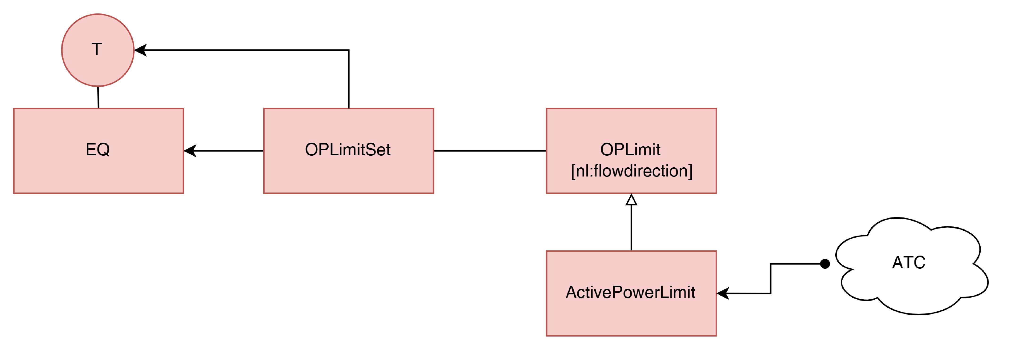
The cim:OperationalLimitSet is associated with a cim:Terminal of a for example cim:PowerTransformerEnd. Which means that the operational limits defined in the OperationalLimitSet apply to the (power) flow through the terminal and equipment combination.
Flow Direction
To support a flow direction the OperationalLimitSet is associated with a Terminal of a piece of Equipment. In combination with the attribute extension nl:PositiveFlowIn in the OperationalLimit object, the direction of the (power) flow is defined. This means that all the operational limits defined in the OperationalLimitSet apply to the power flow through that terminal.
In cim the flow direction for the Operational Limit is not explicit added, bij extending it and adding the standard approach (positiveFlowIn) to the OperationalLimit we do support flow direction in the NBNL EQ profile. see also the Flow Direction page.
Modelling choices
Transformer Limit
In CIM, an Equipment Powerlimit is modelled by a combination of a cim:OperationalLimitSet object and one or more cim:ApparentPowerLimit or cim:ActivePowerLimit objects. The cim:OperationalLimitSet is associated with a cim:Terminal of a cim:PowerTransformerEnd.
Every cim:PowerTransformer has a cim:OperationalLimitSet object associated with the cim:Terminal of the secondairy and where applicable, the tertiary winding (i.e., the winding with cim:TransformerEnd.endNumber=2 or 3).
For 3-winding transformers, two cim:OperationalLimitSet objects are needed, also associated with the cim:Terminal of each winding (i.e., the windings with cim:TransformerEnd.endNumber=2 and cim:TransformerEnd.endNumber=3).
if the limit for the reverse power flow is different a PowerTransformer has an additional OperationalLimitSet, which represents the operating limit for the reverse direction of flow.
Each OperationalLimit object whose Value attribute is populated with a value reflecting the MVA or MW limit for the power flow in the normal direction that is typically used in planning and interconnection studies of the System Operator. The Value incorporates the technical and required policy limits of the System Operator (see also the PATLT (Permanent Admissible Transmission Loading Threshold) definition in the LimitKind)
Circuit/Feeder/Line Limit
In CIM, a limit on a cim:Line (verbinding) or a cim:Feeder (ms-route) is modelled by a combination of a cim:OperationalLimitSet object and one or more Current, Power or Voltage Limit objects. The cim:OperationalLimitSet is associated with a cim:Terminal of a cim:ACLineSegment (or any other cim:ConductingEquipment subtype object associated with a Line or Feeder).
Definitions:
-
a cim:Circuit is a combination of one or more overhead lines between 2 substations for the transmission of energie.
-
a cim:Feeder is a combination of one of more ACLineSegments (cables in series) between a feeding substation and one or more distribution substation or between a distribution substation and one or more end users for the distribution of energie
Every cim:ACLineSegment has at least one cim:OperationalLimitSet object associated with one of its two cim:Terminal objects and can have as many as necessary to accurately reflect the System Operators limit philosophies.
Each cim:OperationalLimitSet associated with a cim:ACLineSegment’s cim:Terminal is associated with a Limit object whose Value attribute is populated with a value reflecting the conductor limit typically used in planning and interconnection studies of the System Operator (PATLT). See the LimitKind
If a device, other than an aclinesegment, is a limiting element on a circuit or feeder, the cim:Equipment subtype object representing the device is associated with the circuit’s cim:Line (via either a cim:Equipment.EquipmentContainer association or via a cim:Equipment.AdditionalEquipmentContainer association) and can have one or more cim:OperationalLimitSet objects associated with one of its cim:Terminal objects.
Redundancy Constraints (e.g., n-1)
Redundancy is an important aspect of grid and therefore there is a need to define operational limits for a group of equipments. The operational limits can be defined for a single piece of equipment, such as a transformer, or for a set of equipment, such as a group of transformers. When set for a group of equipments it can be used to define redundancy, like n-1 configurations. The operational limit is used to define an N-1 constraint.
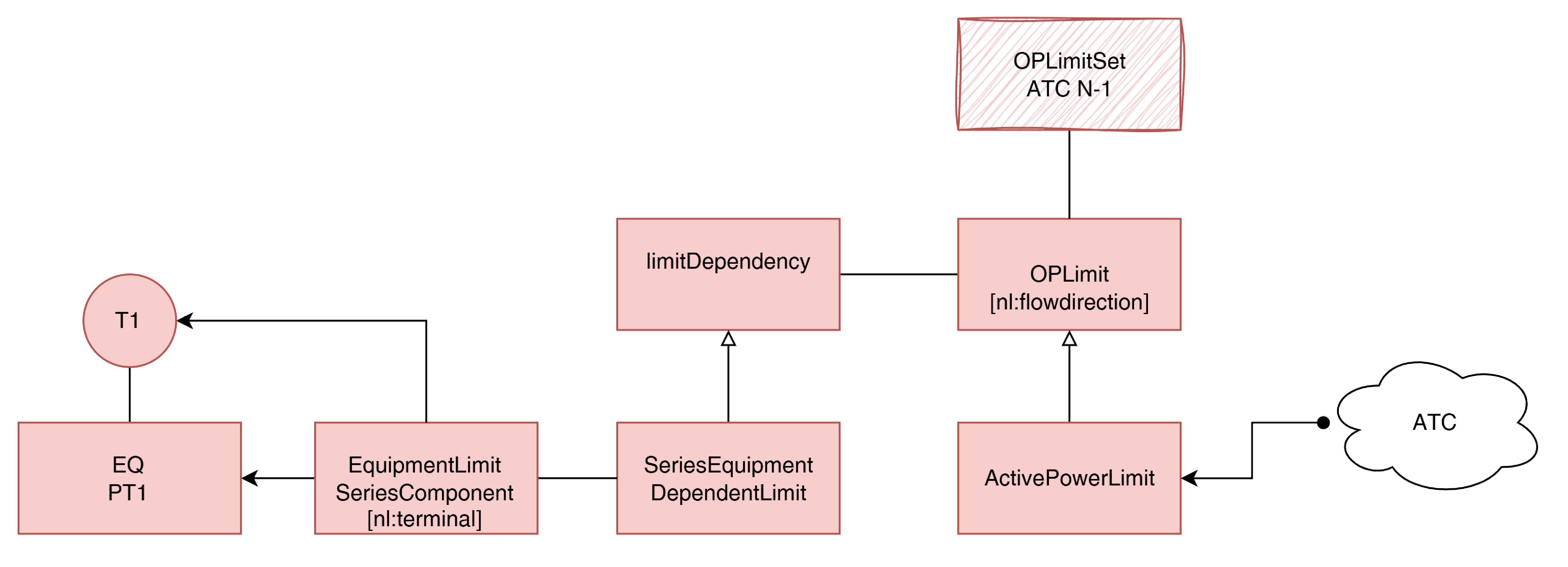
When there is a need to define a constraint based on a grouping of equipment for example in case of redundancy (n-1) then the OperationalLimit has an association available with the cim:ActivePowerLimit.LimitDependencyModel.
The SeriesEquipmentDependentLimit can be used to define redundancy, like n-1 configurations, as a constraint. It can also been used to represent the operational limit of a set of equipment in series (for example a cable (feeder, circuit) based of several ACLineSegments).
Each equipment is added with its terminal (for indicating the flowdirection) to the cim:EquipmentLimitSeriesComponent and associated with the same SeriesEquipmentDependentLimit.
Note
-
In the ofgem LTDS profiles there is also an extension with 2 attributes (validFrom and validTo) which defines the validity period of the operational limit set. It can be used for example for defining summer and winter. This is not implemented in the NBNL EQ profile.
See also LTDS Data Exchange Specifications